This is the first installment of a new blog series on the physics of fatigue. It has been adapted from the upcoming Ph.D. dissertation of VEXTEC’s Robert McDaniels.
Fatigue can best be considered as a process, rather than an event [1, 2]. The fatigue process begins as soon as a component is manufactured and enters service, and proceeds through the life of the component in stages. From the perspective of modeling and simulation, there are 4 stages of the fatigue life of a component:
- crack nucleation: the number of fatigue cycles required to create a crack that spans one grain in a previously un-cracked specimen;
- short crack growth: the number of fatigue cycles required to grow a crack from the crack-nucleated grain until the crack is long enough to be modeled by bulk properties;
- long crack growth: the stage of life when bulk properties can be assumed and conventional linear elastic fracture mechanics (LEFM) is valid; and
- final overload: the stress intensity factor of the component exceeds the plane-strain fracture toughness of the material, and the component fails catastrophically in one additional cycle [2].
The total fatigue life of a component (Nf) can be represented as the sum of the nucleation life (Nn), the short crack growth life (Nsc), the long crack growth life (Nlc), and the final overload cycle:
Nf= Nn + Nsc +Nlc +1
For any given alloy system, the relative fraction of a component’s life that is spent in each stage is controlled by the microstructure of the alloy, the geometry of the component, environmental factors (such as corrosion) and the load history of the component in question.
The Mechanisms of Fatigue Crack Nucleation
While there are as many different types of nucleation mechanisms as there are different types of microstructures, they can all be placed in a few broad categories: fatigue crack nucleation in a material that is free of gross defects (like inclusions), and fatigue crack nucleation in a material that contains gross defects or defect-like features, like notches [3, 4].
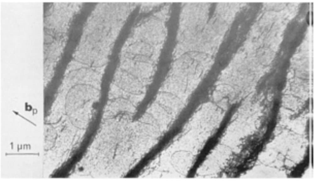
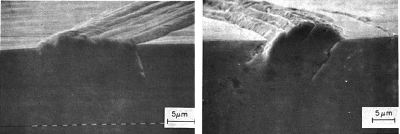
For ductile materials (like face centered cubic [FCC] metals) without defects, cyclic stresses generate dislocations that move due to irreversible slip [3-6]. After continued cyclic loading, these dislocations tend to migrate and pile-up in structures known as persistent slip bands (PSBs). When PSBs migrate to the surface of a ductile metal, a series of extrusions and intrusions are formed. These extrusions and intrusions become stress risers where cracks will eventually nucleate. Figure 1 is a transmission electron microscope (TEM) image that shows dislocation pile-ups that have accumulated to form PSBs [7, 8]. Figure 2 shows a schematic drawing that illustrates the formation of extrusions [5, 7]. Figure 3 shows two images of single crystal copper that have been cyclically loaded. There are PSB protrusions from the polished surface of the specimen, and there are also fatigue cracks that have nucleated and are about 5 micrometers long [9]. This is the nucleation mechanism that is most prevalent in FCC metals like copper (Cu), nickel (Ni), and aluminum (Al).

Figure 1. TEM image showing persistent slip bands (PSBs) in a Cu single crystal. Image from ASM Handbook Vol. 19, pg. 80 (1996) [7,8].

Figure 2. Schematic drawings that illustrate the concept of slip bands [21], and the creation of intrusions and extrusions that are the precursors to fatigue crack nucleation. Image from Dieter pg. 396 (1986) [5,7].

Figure 3. Slip band protrusions in single crystal Cu showing the nucleation of fatigue cracks. Image from Ma and Laird (1989) [9].
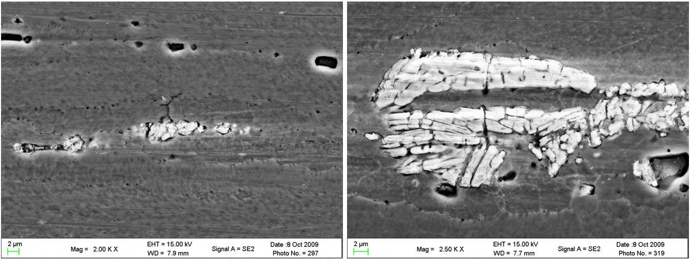
The third type of fatigue crack nucleation is crack nucleation at defects [10, 11]. These defects can take a number of different forms: non metallic inclusions, second phase particles, notches, pores, etc. This mechanism is much more localized, due to the increased stress in the region around the defect due to its stress concentration. Cyclic loading can cause de-bonding between the defect and the matrix, or cracking of the defect itself [10, 11]. In aluminum alloy (AA) 7075-T651, a common aerospace alloy, there is a very large fraction of Fe-containing second phase particles. These particles are more prevalent at grain boundaries, and are of the same length scale as the grains in the L-S plane (which is the plane that has the slowest fatigue crack growth rate). These particles come in many shapes and sizes, and most of them are already cracked after the T-651 strain aging heat treatment to which this alloy is subjected during initial processing. Figure 4 shows two SEM images from a VEXTEC study of AA 7075-T651. The images were taken from a specimen before fatigue testing began. There are many observed cracks in the particles, and the representative crack length is nearly 10 micrometers. This result has also been reported by others [8-20] and is found to be true for all 7XXX series and 2XXX series aluminum alloys. It can therefore be assumed that components made from these aerospace alloys already contain cracks when they are manufactured, and therefore the fatigue crack nucleation life is zero. This is an important determination when it comes to fatigue life prediction, as well as evaluation of these materials’ capacities for damage tolerance.

Figure 4. Cracked Fe-containing particles in AA 7075-T651.
References
- ASTM E 1823-13, “Standard Terminology Relating to Fatigue and Fracture Testing.” ASTM, (2013).
- ASM HANDBOOK Vol 19 Fatigue and Fracture. ASM International. pp. 3-5. (1996).
- Suresh, S. Fatigue of Materials. pp. 132-162. (1998).
- ASM HANDBOOK Vol 19 Fatigue and Fracture. ASM International. pp.48-58. (1996).
- Dieter, G. Mechanical Metallurgy. pp. 394-398. (1986).
- Bannantine, J. Fundamentals of Metal Fatigue Analysis. pg. 244 (1990).
- ASM HANDBOOK Vol 19 Fatigue and Fracture. ASM International. pp.76-86. (1996).
- Mughrabi, H., Ackerman, F. and Herz, K. “Persistent Slip Bands in Fatigued Fac-Centered and Body Centered Cubic Metals”, Fatigue Mechanisms, ASTM STP 675. pp.69-105. (1979).
- Ma, B., and Laird, C. “Overview of Fatigue Behavior in Copper Single Crystals –I. Surface Morphology and Stage I Crack Initiation Sites for Tests at Constant Strain Amplitude”. Acta Metallurgica. Vol. 37, no 2. pp. 325-336. (1989).
- Suresh, S. Fatigue of Materials. pp. 79-83. (1998).
- ASM HANDBOOK Vol 19 Fatigue and Fracture. ASM International. pp. 96 -107 (1996).
- ASM HANDBOOK Vol 19 Fatigue and Fracture. ASM International. pp. 153-158 (1996).
- Kung, C.Y., and Fine, M.E. Fatigue crack initiation and microcrack growth in 2024-T4 and 2124-T4 aluminum alloys, Metallurgical Transactions A 10, 603-610 (1979).
- Laz, P.J., and Hillberry, B.M. Fatigue life predicted from inclusion initiated cracks, International Journal of Fatigue 20, 263-270 (1998).
- Merati, A. A study of nucleation and fatigue behavior of an aerospace aluminum alloy 2024-T3, International Journal of Fatigue 27, 33-44 (2005).
- Weiland, H., Nardiello, J., Zaefferer, S., Cheong, S., Papazian, J., and Raabe, D. Microstructural aspects of crack nucleation during cyclic loading of AA 7075-T651, Engineering Fracture Mechanics 76, 709–714 (2009).
- J., Hochhalter, J.D., Veilleux, M.G., Liu, M., Heber, G., Sintay, S.D., Rollett, A.D., Littlewood, D.J.,Maniatty, A.M., Weiland, H., Christ Jr., R.J., Payne, J., Welsh, G., Harlow, D.G., Waeryzynek, P.A., and Ingreffea, A.R.. A geometrical approach to modeling microstructurally small fatigue crack formation, part I: probablilistic simulation of constituent particle cracking in AA 7075-t651, Modeling Simulation Materials Science 16, 065007, 28 pp (2008).
- Patton G., Rinaldi C., Bre´chet Y., Lormand, G., and Fouge`res, R. Study of fatigue damage in 7010 aluminum alloy, Materials Science and Engineering A 254 (1998).
- Pearson, S. Initiation of fatigue cracks in commercial aluminum alloys and the subsequent propagation of very short cracks, Engineering Fracture Mechanics 7, 235-247 (1975).
- Line, K., McDaniels, R., Pulikollu, R., and Tryon, R. Crack Nucleation Prediction through Surface Roughness Measurement, Phase II, VEXTEC Corp., Brentwood, Tenn., proposal to Defense Advanced Research Projects Agency (DoD). 2009.
- Wood, W.A. Formation of Fatigue Cracks. Philosophical Magazine 3, no. 31, 692-699 (1958).


Leave A Comment